Catania Astrophysical Observatory Laboratory for Detectors
")
")
The instrumental apparatus used for the quantum efficiency measurements has been designed at the Catania Astrophysical Observatory.
The picture shows the system assembled on the optical bench.
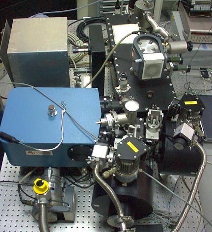
The scheme shown in the following figure allows us to better describe the various parts:
The first module (FIRST MODULE) accommodates an optical system, made up of mirrors and diaphragms, whose purpose is to have the beam emitted by the radiation sources matching the f/5.4 focal ratio of the monochromator.
The sources are a deuterium lamp and a Xenon lamp. The 150 W deuterium lamp is used to cover the 130 - 240 nm spectral range. It is sealed with a magnesium fluoride window. The emitted beam is focused on the entrance slit of the monochromator by two off-axis paraboloidal mirrors (magnesium fluoride coated).
A vacuum flange, inserted on the lamp jacket, allows the accommodation of the source inside the module. The xenon lamp covers the remaining spectral range (240 - 1100 nm) of interest. Being used above 240 nm the lamp is placed outside the module in front of a sealed quartz window. The parallel beam (the lamp's housing accommodate a system of lens) emitted by the lamp is intercepted by a rotating plane mirror and focused on the slit by the second paraboloid.
We have three filters wheels one inside the first module and the other two in front of the xenon lamp outside the module. Two wheels hold interference filters, bandpass filters and longpass filters whose purpose is to filter out the second order and/or to cut down the contribution of the straylight. The third wheel (placed in front of xenon lamp) holds neutral density filters used to reduce the intensity of the input radiation.
The second module along the radiation beam path is the monochromator (model VM504 manufactured by the Acton Research Corporation). It has a Czerny-Turner configuration with a focal length of 0.39 m and an aperture ratio of f/5.4. The monochromator is equipped with three 1200 g/mm ruled gratings to cover most efficiently the whole spectral range.
After being dispersed the radiation beam enters a camera containing a magnesium fluoride beam splitter with a thin film metallic coating (2'' diameter). The beam splitter is optimized at UV wavelengths.
The reflected and transmitted beams are then focused respectively on the reference detector and on the test detector. This task is performed by two "twins'' cameras. The focusing mechanism inside each camera is made up of a magnesium fluoride lens (2'' diameter, 75 mm focal length) placed on a moving frame. The frame runs along two guides and the movement is driven by a step motor. The mechanism has been realized to compensate the variation of the focal length of the lens with the wavelength allowing to have always a focused image of the monochromator's slit on the detectors. The camera on the direct (i.e. transmitted) beam holds also a shutter. These cameras are connected to the beam splitter camera through a gate valve. This expedient allows to switch the reference detector and the test detector while keeping all the system, but the two cameras, under vacuum. As reference detector we use a NIST calibrated photodiode manufactured by International Radiation Detectors.
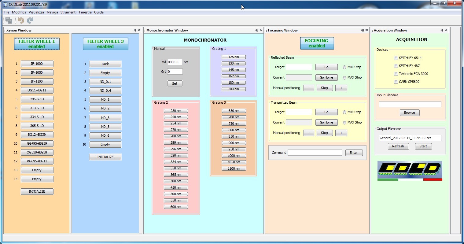
The system is fully automated. In fact all mechanisms are computer controlled. A Visual Basic user interface allows the user to select lamps and filters, to manage the monochromator, to move the focusing lenses and to read the photodiode current. Usually the user selects a wavelength from a list and the software moves accordingly all the mechanisms so to have the correct configuration to start a measurement. The software allows the user to write procedures (macro) to perform complex measurements automatically.
Figure shows how appears the Graphic User Interface at the starting time. This GUI allow us to send commands and acquire/store data.
With regard to the pumping system used for vacuum operations we have four turbomolecular pumps and two dry scroll pumps, used as primary pumps. The turbomolecular pumps are placed directly on the first module, on the monochromator, and on each of the twin cameras. The first two have a pumping speed of 80 l/s (referred to molecular nitrogen), while the other ones have a pumping speed of 50 l/s.